Small and Powerful EVSE Components: MD0630T01A IM-SP401A
To codify the safety requirements for EV chargers, regulatory agencies worldwide have defined standards to which every charger topology must be upheld and are detailed in the IEC 61851 for conductive charging systems. Four charging modes have been defined: Mode 1 involves connecting the vehicle directly to the AC power grid, which is typically not allowed in most countries. Mode 2 requires an intermediate control system (IC-CPD) between the AC power grid and the vehicle to monitor for safety issues and is connected to an AC power outlet socket. This device is usually a mobile device one would carry in the car's trunk. Mode 3 relies on a dedicated safety control system that is permanently connected to the AC power grid; these are the typical AC charging stations seen in many parking lots and garages and installed at private homes. Mode 4 is the only DC-based system, and it converts AC grid energy into DC voltage for charging the vehicle while also monitoring safety. Each of these modes has a dedicated safety standard to govern the performance requirements of the associated equipment. IEC62752 / UL2231-2 is a representative standard for Europe and the USA that covers Mode 2 chargers. IEC62955 / UL2231-2, similarly, covers Mode 3 chargers.
A critical parameter in these types of safety standards is the residual operating current, which is effectively the leakage current that finds a path to ground through some means other than the AC power grid. The residual operating current is a critical parameter because this unknown current path could very well be a human interacting with the system. Therefore, monitoring the magnitude of this current is a primary safety concern. For Mode 2 chargers, the residual current is restricted to 30 mA AC and 6 mA DC. Mode 3 chargers depend on the rated AC current, which residual AC current is allowed. It is 60 mA if the rated current is 125 A, but no AC chargers on the market support more than 22 kW. Therefore realistically, the AC residual current here is also 30 mA maximum. The 6 mA limit applies to both Mode 2 and Mode 3 chargers for residual DC currents.

Charging equipment must contain a highly sensitive device for measuring very small residual current flow in the presence of very large nominal currents to satisfy safety standards. As it is a safety device that can interrupt the charging process, it needs to be reliably working over a wide temperature range with high accuracy. In addition, Mode 3 requires that it withstands up to 3,000 A inrush or short currents without damage.
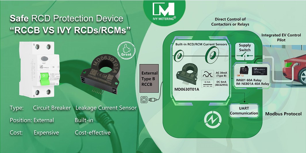
IVY MD Series B-type leakage sensor takes into account both B-type and DC6mA residual current detection. It has digital output and switch output functions, outputs high and low level signals, and integrates self-test function. It can meet the leakage protection requirements of AC charging piles, portable charging piles, photovoltaic combiner boxes, photovoltaic inverters and other application scenarios. It has the advantages of low power consumption, high precision, fast action response, and isolation detection.
Relays play an important role in the safety of EV charging systems and the evolution of PCB-mounted relays brings benefits in terms of cost, reliability and space. Until now PCB relays have been limited to lower-voltage level applications but the IM-SP401A&IM-NE801A relay, capable of handling 40A, represents a real breakthrough for EVSE design. Find out more about IVY’s range of high power relays, including 1 pole IM-SP401A & 2 pole IM-NE801A relay. Alternatively if you’re ready to take the next step with your designs, please don’t hesitate to contact us via ess1@ivy-metering.com


